The main purpose of the Sensor node development is to provide an adaptable device, which will act as a hub for various types of sensors.
The 1st prototype device is based on the STM32F4 microcontroller, which is responsible for the configuration, supervision, and operation of the sensor instruments, as well as performs the function of a bridge between the network controller and the actual sensors. The devices communicate using various interfaces, connectors, and standards, therefore different protocols needed to be handled. The sensor node is compatible with several types of detector instruments:
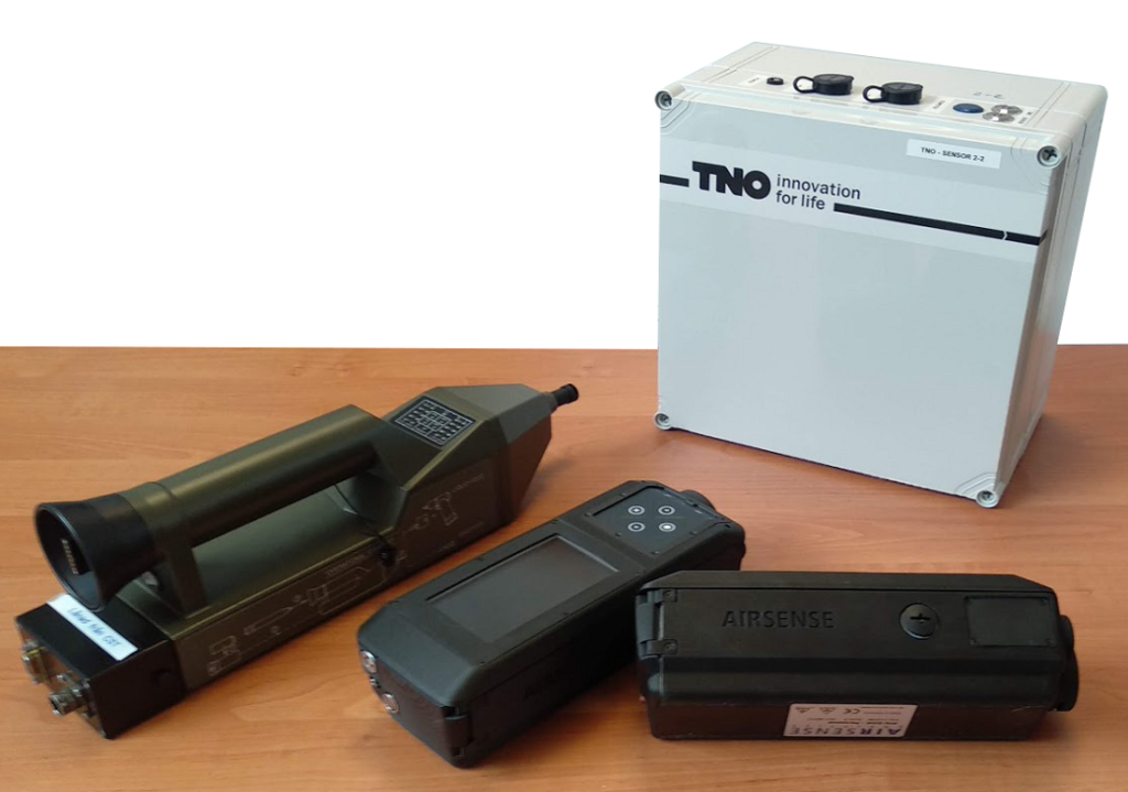
• AIRSENSE GDA-P + EC (Electrochemical cell),
• AIRSENSE GDA-P + PID (Photoionization detector),
• TNO SRD Metal oxide detector,
• Proengin AP4C Flame photometric detector. Support for other devices can be added if transmission protocols are known.
The node configuration is stored on the SD card. After the node startup, the device connects to the individual sensors, runs the measurements and starts receiving data. Every second, the data is collected, verified, preprocessed and transmitted to the network controller. The sensor node is able to wirelessly connect to the network of sensors controller as well as store the raw data on SD card. It is crucial for the system to know the exact position of the sensor nodes. To provide this information, the sensor node box includes a GPS receiver module. The GPS signal may not only be used to determine the location of the device but also to acquire accurate time signature. Both pieces of information are sent together with the data frames.
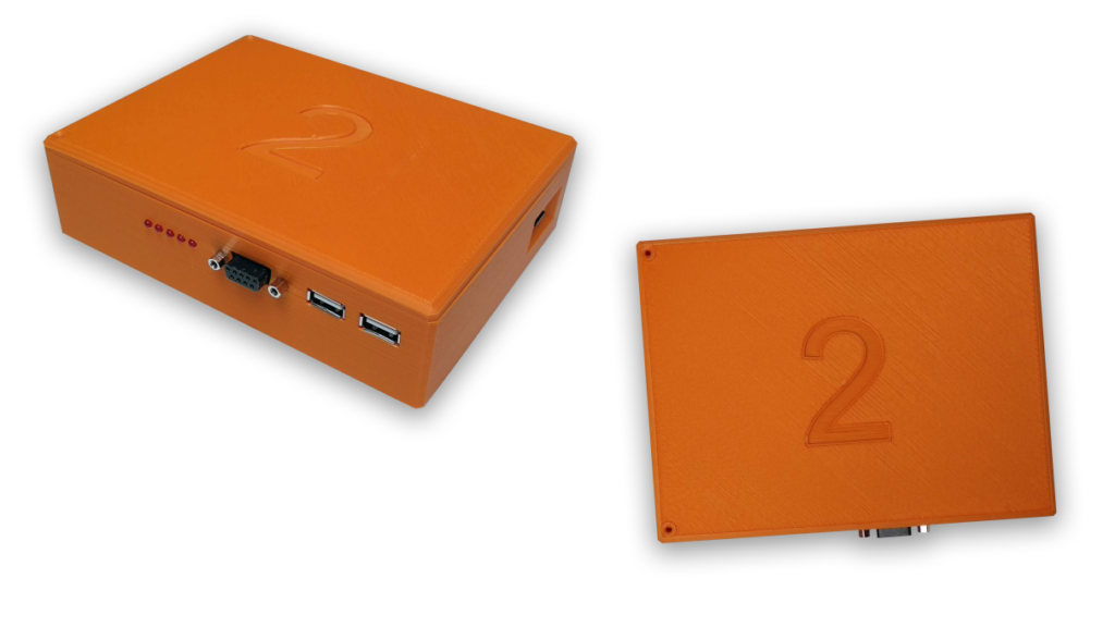
The sensor node casing is 3D printed and includes a set of connectors for the EU-SENSE sensors. On the front, there are two USB sockets for AP4C and SRD devices and the RS232 connector for GDA-P. In addition, the red LEDs are used to signal whether the sensors are working properly. There is also a microSD memory card socket on the right side of the sensor node. The external power supply (e.g. power bank) can be connected through the hole on the opposite side.